TOP / Technology

Technology

Technology

From nano-level processing to surface modification, assembly, and quality-assurance analysis—our integrated technical infrastructure supports our customers’ manufacturing processes.

01

Ultra-Precision Machining

Challenging the Nano-Level

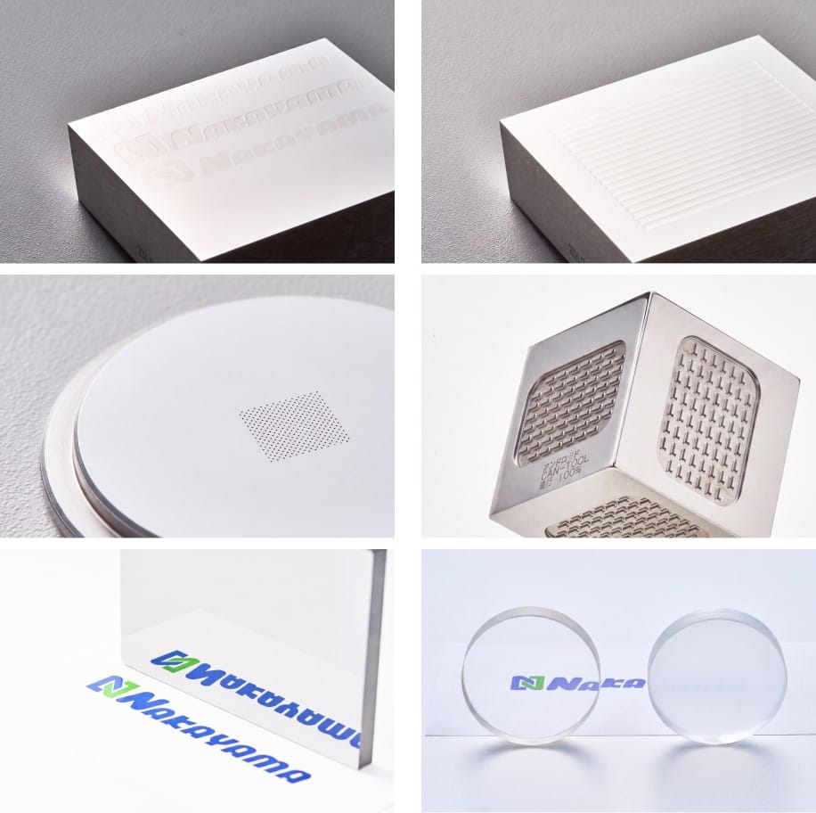
Using the latest Nano Machining Centers and our unique tooling technology, we achieve micro-shapes previously considered impossible. This is highly effective in fields requiring μm-order tolerances, such as lens molds and fuel cell components.

Machining Capabilities & Specs

Surface Roughness (Ra) Single nano level (a few nm)
Min. Hole Dia. Φ0.01mm~
Tolerance ±0.5 μm (Sub-micron)
Key Technologies Direct carving, Mirror grinding, Femtosecond laser
Ultra-Precision Machining
02

Surface Treatment (Coating)

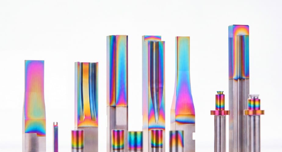
We propose optimal surface modifications tailored to your application, including our original "Soar Coat," which boasts the strongest adhesion in the history of hydrogen-free DLC.
It dramatically improves the durability of mold parts and jigs.

Surface Treatment

Coating Lineup

Soar Coat Original Hydrogen-Free DLC

Strongest adhesion.

Hardness
HV 7000 class
Thickness
0.2〜0.3μm

DLC-EX

Delivers excellent wear resistance and low friction.

Code
DLC-EX
Hardness
3000
Thickness
1〜2μm

ACEX / Al-Cr

ALCr-based coating surpassing the limits of TiAlN.

Code
ACEX
Hardness
HV 3000
Thickness
0.5μm – 3.0μm

ZPC / Zac Super

Next-gen coating with excellent wear & thermal shock resistance.

Code
ZPC
Hardness
HV 3400
Thickness
1-2μm, 3-4μm
03

Equipment Assembly

Equipment Assembly
Equipment Assembly
Equipment Assembly

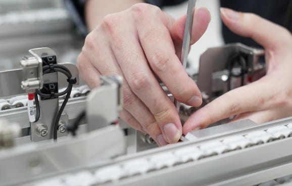
Flexible Scope of Services and Proven Assembly Technology

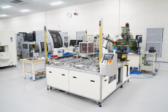
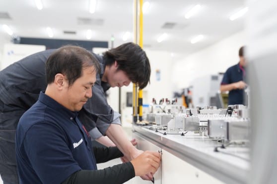
We have a dedicated assembly facility where we assemble high-precision units and equipment, as well as control panels, in a clean environment.
We offer flexible solutions tailored to our customers’ needs, ranging from the design phase alone to end-to-end support for the entire system.

Design

• Mechanical Design
• Electrical Design
• PLC Software Design

Equipment Assembly

• Parts Procurement
• Assembly
• Wiring

Adjustment/Inspection

• General Operations
• Flow
• Product Inspection

List of Past Equipment Manufacturing Projects (Excerpt)

We listen to our customers’ on-site needs to implement the optimal automation solution.

Automation Equipment

  • Automated Material Handling, Product Positioning, and Assembly
  • Visual and dimensional inspections using an image processing system
  • Cleanroom Design and Electrostatic Discharge (ESD) Countermeasures
  • Production line with hoop feed

Proven Equipment

  • Pressure Testing Equipment
  • Refilling Machine
  • Press-Fitting Machine
  • Image Inspection Machine
  • Packaging Machine

Equipment for FA, Research, and Other Purposes

Proteome Electrophoresis System

Protein Separation System for Medical Research (High-Voltage Application and Robotic Handling)

Proteome Electrophoresis System

Proteome Electrophoresis System

Laser Marking Machine

Laser Marking of Parts via Automatic Feeding

Laser Marking Machine

Laser Marking Machine

Rolling Thunder III

Custom-designed processing equipment for various types of round parts, including machining and deburring

Rolling Thunder III

Rolling Thunder III

Automatic Electrode Cleaning Machine (Using Collaborative Robots)

Automated, unmanned handling of electrodes, cleaning with cleaning solution, air-blow drying, and storage

Automatic Electrode Cleaning Machine (Using Collaborative Robots)

Automatic Electrode Cleaning Machine (Using Collaborative Robots)

04

Inspection / Analysis

Visualizing “hidden defects” and guiding the process from identifying causes to implementing improvements

“I want to know the surface roughness of round parts.”
“I want to take high-magnification photos to inspect products.”
“I want to check whether any foreign particles are adhering to parts.”
“I want to determine the size of foreign particles and review our quality control system.”
Our state-of-the-art analytical equipment and dedicated staff are here to address the various questions and challenges that arise on the shop floor.

Inspection / Analysis

We go beyond mere measurement; we conduct surveys using a consistent workflow consisting of “observation” → “measurement” → “analysis” → “reporting.”
We provide comprehensive support, from identifying the causes of defects to proposing specific improvements.

Measurement and Analysis Process

01. Observation

We inspect the color, shape, and other characteristics to check for any abnormalities.

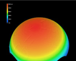
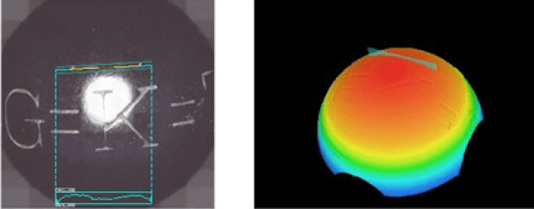
3D Observation
3D Observation

Even small scratches that aren’t visible in photos can be observed and detected in three dimensions using a 3D comparison view.

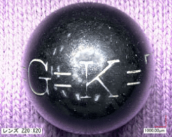
High-Magnification Photography and Image Stitching

Using a digital microscope, take a photo in which everything is in focus using the image stitching function. This is ideal for initial shape observation.

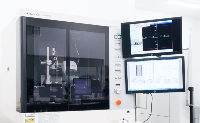
Machines Used: ・Measurement and Analysis Microscope (VHX-7000) ・Laser microscope (VKX-1000)

02. Measurement

We accurately quantify the observation points.

Roughness and Depth Measurement

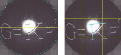
It measures even minute surface roughness, including that on spherical surfaces, which is considered difficult to evaluate. It is also capable of measuring depth at any location.

Spherical and Planar Measurement

It accurately measures the radius of a sphere and any distance or dimension on a plane.

Machines Used: ・Laser Microscope for Shape Measurement (VK-X200)

03. Analysis

We will break down the elements to determine their nature. We will conduct the analysis in collaboration with internal departments and certain prefectural agencies.

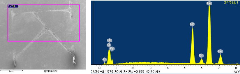
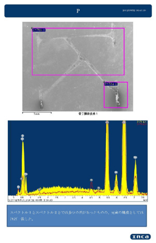
Composition Analysis

We analyze the elements present in a sample. For example, we identify what a “foreign substance” adhering to a surface is, which provides a clue for determining the cause.

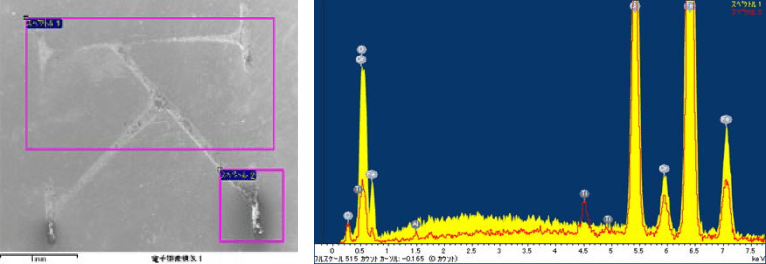
Comparative Analysis

By comparing the analysis results of good and defective products, we present the differences in a clearer and more understandable way.

Machines Used: ・3D Real Surface View Microscope (VE-8800)

04. Report

We’ll summarize the results and use them to develop solutions.

Detailed Report
Submit a Detailed Report

We compile the various data and high-resolution images obtained through observation, measurement, and analysis, and prepare and submit easy-to-understand reports.

Feedback for Improvement

Based on the identified causes, you can use this data to review your product quality control system and improve processing conditions.

Fluid Simulation (CAE Analysis)

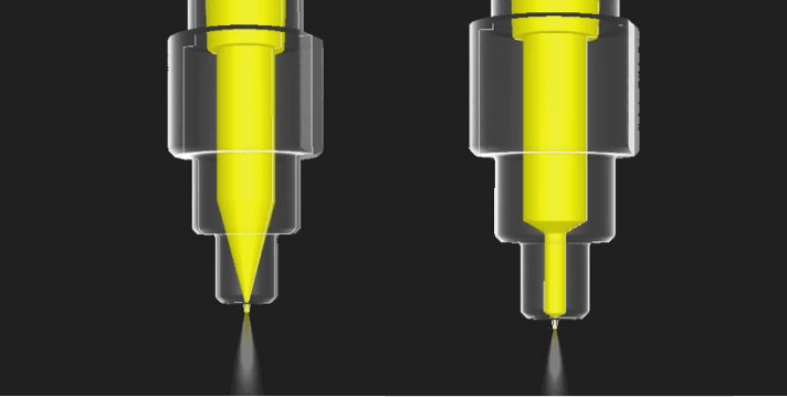
Using the “scFLOW” software, we predict the behavior of resin dispensed from the nozzle and visualize the airflow within the pickup tool. This is effective for understanding phenomena that are difficult to observe in practice and for significantly reducing the number of prototypes and costs during part production.

Fluid Simulation

Analysis Case Study: Optimization of Coating Nozzles

This simulation models the spread of resin dispensed from a dispenser nozzle.
By varying part parameters—such as “internal nozzle geometry,” “tip wall thickness,” and “discharge orifice diameter”—and fluid properties—such as “resin viscosity” and “surface tension”—we perform analyses to identify the optimal dispensing conditions.

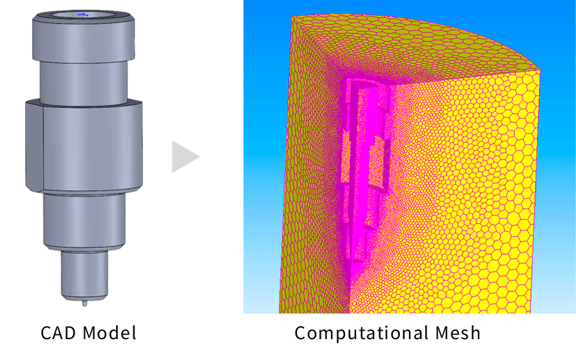
Set the analysis conditions and create the mesh, which serves as the basic unit for the calculations.

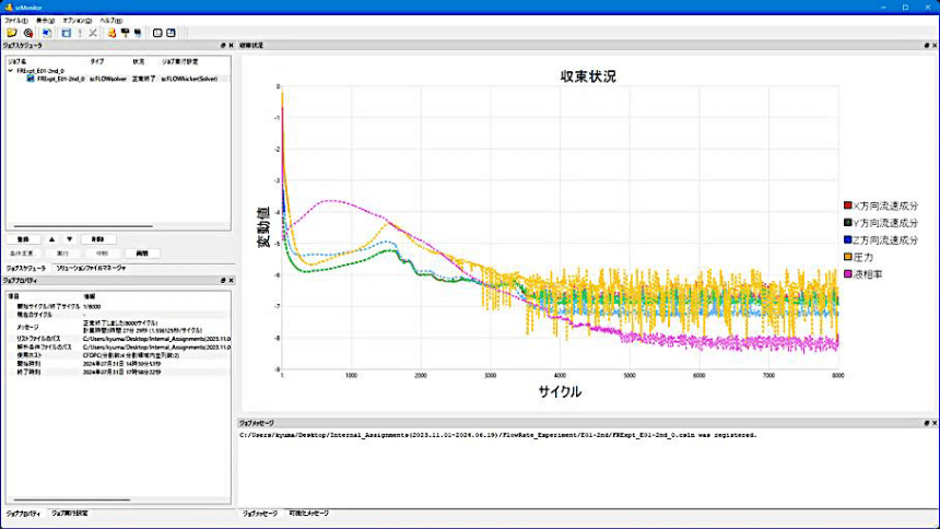
Calculate fluid motion at each mesh point.

MOVIE: Simulation Footage

Visualization of computed fluid motion. You can see how the resin flows and is dispensed inside the actual nozzle.

SOLVE YOUR MANUFACTURING CHALLENGES

From prototype development to mass production supply chain stability. Contact us today to discuss your project requirements.

Request a Quote